This project has been simmering on the back burner for a very long time now. I only recently got a chance to scrounge up a round-tuit in order to get this thing done.
With the advent of the Arduino hardware ecosystem has come a general bar-lowering for people doing all kinds of projects. This especially holds true for those of us building simulators of various stripes. You can find Arudino-based gadgets driving instruments and masquerading as all kinds of little cockpit gadgets these days.
One of the holes in this has been a genuinely easy to use flight control interface based on the Arduino. Well with the introduction of the MMJoy2 firmware as written by “mega_mozg”, this hole has been filled.
mega_mozg’s firmware can run on a number of different Arduino & Teensy boards, but for this article I’m going to focus on the ATMega32U4 based Pro Micro. This device can be had from SparkFun for about $20 here (you want the 5v version). You can also purchase Pro Micro clones from overseas eBay vendors for as little as $6 plus shipping.
Using the Pro Micro as a base, it’s pretty easy to create a six axis, 32 button joystick interface that you can customize in just about any way you like.
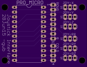
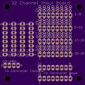
In order to make this pretty easy to do, I created a couple of printed circuit boards. One is the “main” interface board that you plug the Pro Micro into. It has six 3 pin headers for the axis inputs and a 4 and 8 pin header for connection to the the second board. The second board provides an 8×4, diode isolated input matrix. This is how you can connect 32 buttons. The diodes allow for “n-key rollover”. You can close all the switches at once and each one will still register individually.
The two links below are a set of Gerber files that you can send to Osh Park to have boards made for you. Their pricing is excellent and their service is even better. Other vendors may be able to process the Osh Park gerber files, but no guarantees.
Pro Micro Joystick Interface-28Jun15-1
32 Channel Input Board – 08Jul15
If you like, you can order 3 of each board directly from Osh Park by using the following two links:
https://oshpark.com/shared_projects/fULmditL
https://oshpark.com/shared_projects/SsFjqyuj
When you solder up the 32 channel input board, you’ll need 32 1N4148 diodes. Bend them in half and solder them in with the black band (cathode) “facing” the board. If you zoom into the photo below, you’ll see what I mean. You’ll also need 9 8 pin headers and 1 4 pin header for each board. You can save some money by buying 1×40 straight headers and break them up into 8 pin headers yourself. All Electronics has them for pretty cheap here. I’m sure with a little digging you could find them for even less from an overseas eBay vendor.
You’ll also need to build two interconnect cables – 1 4 wire and 1 8 wire. I really like the look of crimped connectors and their shells, so I build up my own cabling. You can find both 4 and 8 pin connector shells and the crimp on female connectors at Hansen Hobbies. They’re a great bunch of people and they ship fast! Here’s the page you want. Order the Female Gold Terminals for .100 and the 1×4 and 1×8 connector shells. It also looks like they sell the 1×40 snappable headers for less than All Electronics!
For the Pro Micro interface board, you’ll need one of these. It’s like the snappable 40 pin header, but it’s a female connector. You’ll lose one position for each break, but you only need 2 12 pin connectors out of the 40 available. Note that while the Pro Micro has the same footprint as a large 24 pin IC, I recommend against using a chip socket. The .100 pins that the Pro Micro uses are too large for the pin pockets in a normal IC socket and they’ll be damaged and may not grip the pins properly.
To finish the interface board, you’ll need six 3 pin headers, so order enough of the 1×40 snappable headers to get the job done for both boards!
You’ll also want to purchase six 1×3 female connectors and their pins in order to connect pots or hall effect sensors to the board.
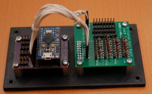
This is what the system looks like as-built:
The two boards are mounted to a 3D printed panel that’s 5mm thick and attached with 8 1/2″ 4-40 M-F standoffs. Worked out pretty well!
If you’ve got a 3D printer, you can download the STL file for that mounting plate here – Joystick Interface Mounts. The zip file also contains a DXF file that you can use if you want to create a drilling pattern for mounting the boards on something other than a 3D printed panel.
The 32 channel input board was originally going to be used with a different project, so it includes an extra 8 pin header that’s not used.
The software you’ll need to run on the ProMicro can be found here. The original site is in Russian, so I’ve given you the Google Translate link for it. You’ll also want this PDF file. It’s a how-to I wrote back in February on how you can upload the MMJoy2 firmware to the Pro Micro without having a special programmer. It’s a very simple and straightforward process!
Below is a zip file that contains the configuration data used by mega_mozg’s JoySetup program. Once you’ve got the MMJoy2 firmware uploaded to your Pro Micro, you can pre-configure the interface using those configuration files. You’ll probably want to rename the device – it’s currently labeled for use as the Roll, Pitch, and Yaw interface for my F-15C project. 🙂
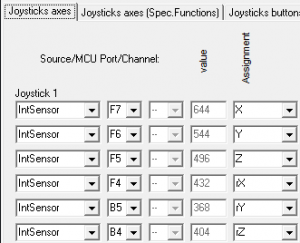
If you don’t want to use my configuration, you can configure the firmware using JoyTest and the diagram shown below.
In JoyTest, click on the “Joysticks axes” tab and change the Source and MCU Port drop-downs to match what’s shown below.
Next, click on the “Joysticks buttons” tab and set up the button matrix rows and button matrix columns drop-downs to match the figure below.
In order to save your changes to the Pro Micro, you’ll need to click on the “Save sets to device” button. I highly recommend that you also click the “Save sets to file” button in order to create a backup configuration on disk.
The interface will read either potentiometer in their 3 wire configuration, or hall effect sensors like those made by Allegro.
The axis input connectors are clearly labeled as to which axis you’re connecting to. Pin #1 (as marked on the left) is the signal input. Pin #2 is Vcc (+5v from the USB interface) and pin #3 is the ground. I arranged the pins like this to prevent any damage to the Pro Micro if you plug the connector in wrong. No matter what, Vcc remains in the center and can’t be shorted out by reversing the connector.
You’ll note that the position values displayed both in JoySetup and the Windows Game Controller panel will vary wildly if there’s nothing connected to the individual axis inputs. If you don’t need all six, you can either disable the un-needed ones in the JoySetup program, or you can attach a jumper between pins 1 and 2 on the 3 pin joystick header. This will have the effect of “pinning” that particular axis to it’s largest value.
Connecting things to the input board is pretty straightforward.
You’ll connect your four pin cable to the header marked “COLUMNS” and your eight pin cable to “J1” directly to the right of the COLUMNS connector. J8 is unused.
Each of the columns are wired together and work in conjunction with the row inputs along the right half of the board.
C-1 handles inputs 1-8, C-2 handles 9-16, etc. In order to wire in a switch, you’ll connect one pin from the column connectors to your one leg of your switch and the other leg of the switch will be connected to one of the row pins. The row headers have their pin #1 on the leftmost position of each 8 pin header.
That’s all there is to it!

![Pins_Sparkfun[promicro]-geneb](http://www.simpits.org/geneb/wp-content/uploads/2015/07/Pins_Sparkfunpromicro-geneb-300x223.png)


Gene, many thanks for the idea and just received my OSH PARK PCB’s. I am having trouble in getting the male pins into the thru-holes for the Pro-Micro. The holes are smaller when compared to the others in the Pcb.
Cheers
Luis
Luis, I assemble them using “machined pin” chip sockets that also require machined pins to be on the Arduino itself. I don’t use the stock .100 pins that they’re shipped with because they tend to ruin “cheap” chip sockets.
Thanks for the important info, I hope they are the ones you have in the links of your post? I ordered quite a few.
Cheers
Luis
Luis, you’re going to have to refresh my memory – what links are you referencing?
g.
just saw your note, meant Hansen Hobbies link.
I am trying to use the MMJoy2 to rebuild my 737 CDU keyboard.
Search google for “machined pin header” and look at the 2nd or third row of images (the non-sponsored ones). That’s what machined pin sockets & headers look like. Those are only used for the Arduino, not the axis, row and column connections.
Hello Gene,
Please can you help me, I have a very old F-16 TQS (REV CODE F-072669-Gameport) I’m trying to revive it, I have this ATMEGA32u4 5v 16 MHZ card, how to upgrade in TQS, and also use Hall sensor in TQS, this project Simple to build joystick interface, can be used in TQS ??
Is there any kind of modification ???
I await your response
Thank you !!!
The joystick interface I show in the blog entry will work with any 3 wire pot or hall sensor. If the TQS is a game port device, the pots used may only be 2 wire, in which case you can’t use them. I’ve never owned a TQS so I don’t know what would be involved in rebuilding it for use with a sim.
Hello Gene,
Please can you help me, I have an F-16 TQS (REV CODE F-072669-Gameport), I have this board ATMEGA32u4 5v 16 MHZ, how to upgrade in TQS, and also use Hall sensor in TQS, this project Simple to build joystick interface, which you developed applies to TQS as well.
Do you have to make any changes to the PCB ??
Thank you !!!
Gene would like to send you some pictures of the device ??
Sorry for asking the same question.
Thank you !!!