The past couple of weeks has brought some good progress to the simulator hardware. It’s still not flyable yet, but it’s a lot closer than it was in December!
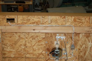
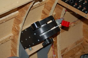
The main wiring harness for the pitch & roll axes gimbal and the stick wiring was installed:
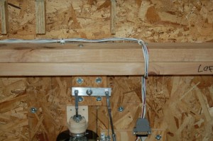
I used cable clamps to attach the harness to the underside of the cockpit. To separate the side from the center, you only need to unplug the harness from the gimbal assembly and remove one cable clamp.
It turned out nicely and while I should have combed out the wires (makes a better harness) it’s great for the prototype wiring.
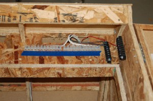
As you can see, the harness passes up into the cockpit via a square cutout in the floor side. This brings it up to a top side terminal block:
The black terminal blocks are for the common ground that the switch inputs and potentiometers use and the +5VDC used by the potentiometers alone.
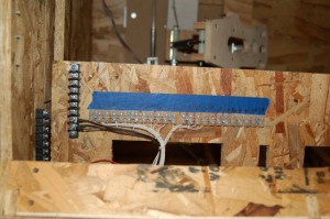
Here’s a bit of a better view of how it’s wired. Pretty easy to do. I’m using the “Euro” style terminal block for the signal wiring because it’s more compact and doesn’t require that I add spade lug connectors to the wiring. Less expensive too.
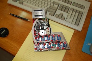
The left sub-panel is complete! Here’s what the final wiring looks like:
It’s really tightly packed in there. The panel really should be a bit wider to accommodate the amount of wiring that’s there – as it is, the panel has to be twisted and turned to get it to fit into the instrument panel. I’ll update the design for the unit that will go into the #1 cockpit.
This leads me to a bit of an explanation as to what I’m going for here. The cockpit I’m working on right now I refer to the #0 cockpit. It’s the first one I built and I’m using it kind of as a test article to try out various wiring & control setups. The idea is to experiment with different layouts & configurations in order to find all the little “gotchas” before I complete the interior of the #1 cockpit. The #1 cockpit was built in order to write the manual on how to build it. 🙂 Because of that, I used more expensive materials (MDF as opposed to OSB) and the design errors found during the construction of #0 were corrected for #1. When #0 is fitted out the way I like it, most of the components will either be duplicated or transferred into the #1 as appropriate.
Over at SimHQ a guy has put together a really cool variant of my take on Mike’s throttle quadrant design. He’s using regular rotary pots for the levers and has skinned his in 1mm ABS plastic.
Because I had made a mistake wiring up the pots in my throttle quadrant (I flipped the wiper and ground wires so nothing worked) I had to tear it completely down. I took that opportunity to drop the propeller pitch lever in order to thin the quadrant down a bit. Because of how nicely Metalinwood’s quadrant turned out when skinned in ABS, I went to a local plastic supplier and got some .060 black ABS that had a light texture on one side. The sad thing is that I only needed an 18″ x 3-3/8″ piece, but they only sell it by the full sheet. I have a 4×8 sheet of ABS to find a use for. I’m sure I can come up with something. 🙂 I’ve never worked with ABS plastic before and I’d never done any thermo-forming either. I turned out VERY easy to do as long as you’re careful and don’t overheat the material. I used a heat gun with a wide, flat nozzle and it turned out great!
Here’s the result of the rebuild:
I’m still on the fence on whether or not I’ll paint it gray like the support pedestal and the quadrant sides. The whole black & silver contrast looks neat.
I’ve ordered a set of bearings from the source mentioned in the SimHQ thread – I’m going to try his method for the quadrant that will be built for the #1 cockpit.
Until next time, here’s the video I took of the first control test. That’s the day I found out I had a big problem with the quadrant, but not what it was.
httpv://www.youtube.com/watch?v=PxGICmW2lwI
