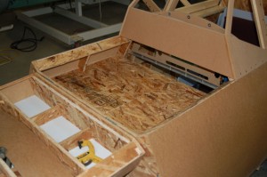
In order to have space for wiring and power supplies, I decided to add a forward deck to the cockpit ahead of the instrument panel:
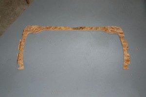
There are two of these support assemblies. Each one is made of two side ribs with “expanded” stringer notches, a single cross-piece and two doubler plates. It’s assembled with six #10-24 screws on each side and the screws go into #10 T-nuts. I’ll be making the drawings for these parts available to those that have purchased the project CD.
The deck itself is made of two pieces. Each one is notched to accommodate the center rib as you can see in the photo. The deck itself is just slightly higher than the instrument panel and a stiffening brace can be installed between the panel and the deck support if you feel the need.
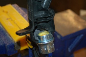
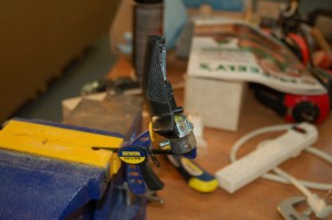
The grip I’m using for this cockpit is a rebuilt Suncom SFS F-15 Eagle grip. In order to mount it to the 3/4″ EMT mounting post in the SFS box, I needed to attach a 3/4″ female EMT pipe fitting to the grip base.
I used a “steel epoxy” called JB Weld to ensure that the joint would be secure. The fitting is mounted in the outside half of the grip. By attaching it to half of the grip, I’ll be able to tear the grip down for maintenance if needed.
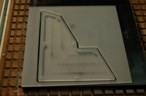
I was also able to get the edge-lit panel machined for the left sub-panel in the cockpit. Here’s a picture of it right off the ‘bot:
The stock material is .25″ P95 translucent white acrylic. I chose this because of it’s amazing light diffusing properties. The pocket in the panel is .20″ deep, leaving me about .05″ of material left.
The next steps will involve creating an alignment jig for the laser and then the switch holes will be cut, the panel will be painted and then it will be lettered.
Finally, here’s a short video of the progress so far:
