Now that all the parts are cut and everything fits like it should, It’s time to move on to getting this thing assembled!
I made one more change to the original BRFS design:
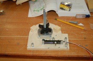
Instead of using the recommended method for keeping the main support bolt from rotating when you tighten or loosen the friction knob, I installed a stove carriage bolt that has a squared area right underneath the bolt head. This prevents the bolt from turning once it’s drawn completely into the material.
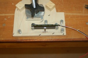
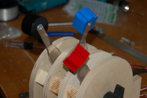
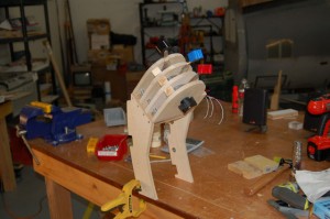
The first step is to get each lever rigged up:
The rigging line I used was 36 strand steel beading wire. This and the swag collars can be had at your local craft store.
I’m using a pull-pull system to actuate the slide pot – the geometry is similar to the BRFS throttle, but because my levers are symmetrical, I didn’t need to use the spring to keep tension on the line. I’ve also drilled two holes (only one is used) to attach the pull wires to the pot arm. Each hole that the rigging wire passes through has been carefully de-burred in order to make sure that no sharp edges existed that could cut the line over time.
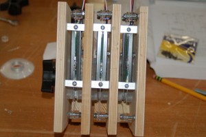
This is what it looks like from the bottom with all three lever assemblies installed.
The knobs are painted and they turned out really nice!
(don’t forget to click the “more” link below!)
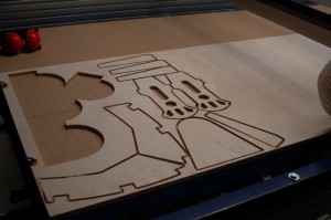
I hate wasting raw material, especially when I’m using 1/2″ Baltic Birch. The stuff is crazy expensive around here. I had a number of parts I needed to cut out, including the throttle quadrant mount, so I combined a few projects worth of parts in a single ShopBot session:
From left to right – throttle quadrant supports, trim & flap wheel center support, replacement rudder pedals and rudder pedal supports.
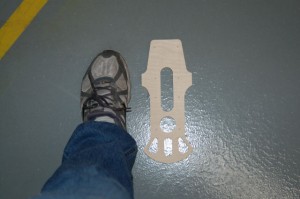
The rudder pedal is an Imperial dimension version of Baloo’s fantastic metric pedal design. His original pedal design was an all metal part. I’ll be posting the drawing files for my pedal as well as Baloo’s original plans in the near future. Here’s a shot that’ll give you an idea of how big the pedal is. My shoes are size 11-1/2″:
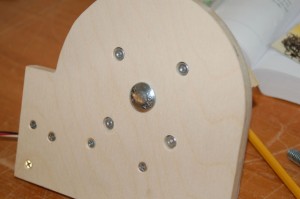
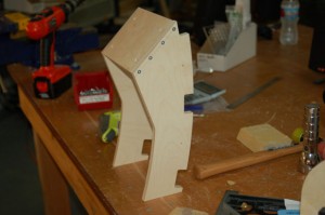
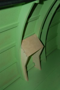
The throttle quadrant support is contoured to follow the rib pattern in the cockpit in order to make it fit as well as possible. The support sides are made from 1/2″ Baltic Birch and the quadrant deck is made from 3/4″ A1 Birch, but you could use any good plywood of similar thicknesses.
Here’s what the support looks like installed:
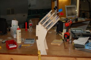
The quadrant support is just a little over 13″ tall.
Here’s what the quadrant looks like attached to it’s mount:
When I get a chance to get the support painted, and the throttle quadrant skinned, I’ll post pics of both installed in the cockpit.
More soon!
Re: Stove Bolt – I think you meant “Carriage Bolt”.
Fixed! Thanks for pointing that out.
Hi, thats looking really good, I hadnt seen this design before. I am going to to a p38 quadrant and this looks a lot easier then gearing for a standard pot.
What size slider are you using? Ps I am envious that you have the shopbot, I am halfway through a 4×4 cnc router so I am doing this one by hand!
Thanks,
Jason
Jason, the slide pot is a 60mm pot.
I’ve got a template in the works for adapting the grip of a Saitek X45 throttle to the BRFS throttle quadrant. Hopefully I’ll get something done on that this coming week.
g.
I don’t know how I came across this but it’s really cool. I used to dream of doing stuff like this in the 90s, make a 1:1 F/A18 cockpit and have it 6″ off the ground in my warehouse so you had to climb in on a ladder. No ware house and no time these days, I’ll just watch!
Wow u rock man good job how is the the slide pot wired into the system thanks
At the time it was wired into to a Beta Innovations Plasma MM2 controller. Any controller would work though. (Leo Bodnar’s stuff, a Teensy, etc.)