Archives

All posts for the month January, 2010

…but before that…

I replaced the Plasma V2 with a Plasma MM2 that I had.  Turns out that the P2 was the core of all my controllability problems.  Once I installed the MM2, it was a whole ‘nuther ballgame.  No more crazy spikes or sluggish control inputs.  It was pretty damn nice actually. 🙂

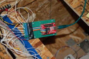
Here’s the board I put together in order to interface the MM2:

What kills me is that this device is no longer available.

Another change I made was to the return springs that were in the pitch axis mechanism.  The original springs weren’t up to the task with the amount of weight in the grip & interface box.  The stick would stay where ever I let go of it.  The springs I use are compression springs that are 2″ long and made from .072″ diameter wire.  I changed to a 2.50″ spring made of .080 wire.  This made a big difference for a small change.  The pitch axis now returns to center the way it should.  However, the feel is still a bit weak so I may change that to an even stiffer spring.

Ok, now back to the title of this entry…

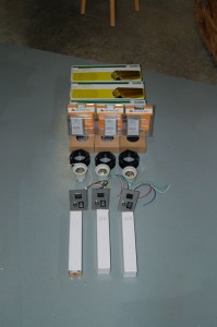
I ordered three projector kits on the 31st of December.  After an agonizing wait they were finally shipped.  Here’s some of the parts:

The kit consists of optics (220mm & 330mm fresnel lenses and a 330mm “triplet” output lens), power panel, 400W Metal-Halide lamp (that the 12 year old in me has christened The Photon Phallus. *snickers*), Mogul base for the lamp, temperature controller for the fan, a fan and a 400W ballast for the lamp.  All of this neat stuff is available from DIY Projector Kits (http://www.diyprojectorkits.com).

Be warned, the plans (at least for the one I have, the S-15) are VERY, VERY, VERY vague.  If you get one and have questions, either see my build thread on the site (“geneb’s triple threat”) or email me directly.  My build thread will do what it can to rectify the captionless pictures that comprise some of the documentation. 😀

On the 23rd, I spent the day doing maintenance work on the ShopBot, including adding a 1/32″ gasket to all the vacuum zones.  The gasket drastically improved the performance of the vacuum hold down system.  I then got all the parts cut for the projector cases.  I used 18mm (3/4″) Baltic Birch.

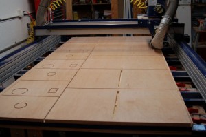
Here’s the first of two sheets that were cut:

The parts in the foreground with the long slot in the center is the projector top.  The slot is the air intake for the lamp cooling fan.  It draws air in-between the “cassette” that holds the 15.4″ LCD panel and the cassette that holds the collimating fresnel.  You’ll see pictures of these things in the coming days.

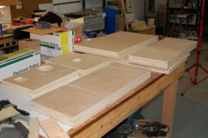
Here’s the stack of parts that resulted from yesterday’s run:

The next steps are to mark & drill the case parts for the pocket screws I’m going to use for assembly and make the LCD and fresnel cassettes….

To hold you over till next time, here’s a video I shot of the beta version of the avionics system I’ll be using in the cockpit:

httpv://www.youtube.com/watch?v=1X69mIBtyu0
The past couple of weeks has brought some good progress to the simulator hardware.  It’s still not flyable yet, but it’s a lot closer than it was in December!

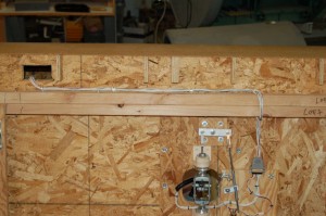
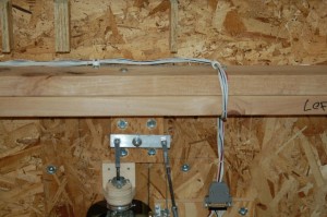
The main wiring harness for the pitch & roll axes gimbal and the stick wiring was installed:

I used cable clamps to attach the harness to the underside of the cockpit.  To separate the side from the center, you only need to unplug the harness from the gimbal assembly and remove one cable clamp.

It turned out nicely and while I should have combed out the wires (makes a better harness) it’s great for the prototype wiring.

Continue Reading

The goal was to be able to “fly” the 109F/X by the end of the year.  I didn’t make it unfortunately.  However, things are looking good for a 1st week of 2010!

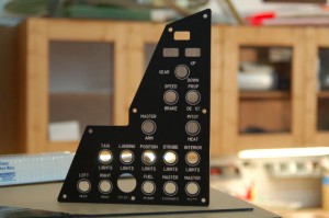
First up, here’s the completed edge-lit panel for the left sub-panel:

The only problem with the panel is due to a “mid-course” design change that I made.  Instead of making the edge-lit panel and metal back plate mounting separate, I decided to combine the two.  Since I had done all the panel lettering before I made this change, things on the bottom row kind of got a bit messed up.  It’s only really noticeable where the mounting screw passes through the STARTER legend.  If I was making this panel for someone else, I would remake it to correct the error.

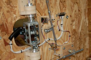
The wiring on the pitch & roll axis gimbal is now completed.  Now that the flight grip has been wired up, it was time to finish out the wiring harness on the gimbal assembly:

This adds the 16 wires that are needed by the flight grip and the nose wheel/AP disconnect lever.  Instead of using tie-wraps to create the new harness, I used waxed lacing cord and then used tie-wraps to attach the harness to nylon cable keeper blocks that have been attached to the gimbal base.  The last 6″ or so of the harness up to the DB25 connector is covered with a 1/2″ diameter black plastic split “loom” cover.  Makes it look nicer and prevents the wire from being abraded.

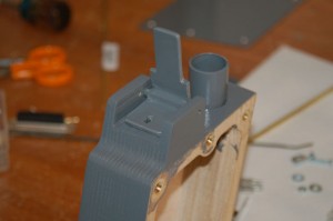
I had gotten the SFS box painted the previous evening and now it was time to mount the nose wheel steering/ap disconnect lever to the top of the box:

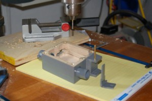
Instead of using a screw & bolt arrangement to hold the NWS/AP lever in, I decided to drill the hole in the side ears just a tiny bit under .125″ and use a brass pin to hold the lever in.  In order to properly set the pin, I turned my drill press into an impromptu arbor press by using a 3/32″ drill bit mounted backwards in the drill chuck.  I also gave the pin a slight bevel around the ends to make entering the mounting holes easier.  Here’s the result:

The pin pressed in just as I’d hoped and it won’t work itself out over time.  The good part about using the method I did is that the pin can be easily removed in the same manner it was installed if I need to replace or repair the lever in the future.

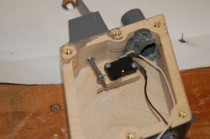
Now that the lever is in, it was time for the switch:

To actuate the micro-switch, I’m using a short length of #4-40 threaded rod as an actuator and a small spring to give it more “pull” than would be provided by the internal spring in the micro-switch.  I was able to thread the micro-switch actuating lever with a #4-40 tap.  There’s only enough metal for one thread or so, but it works really well!  I’m going to put a dab of Loc-Tite on it to help it out.

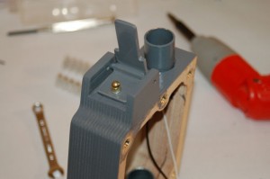
To retain the actuator rod, I used a brass acorn nut at the top:

There is a small metal cover that still needs to be made that will cover the front portion of the NWS/AP lever.

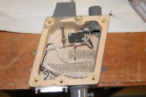
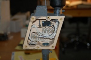
The internal wiring of the box took some time to complete and there was not a whole lot of room in there:

In order to make it more friendly to repair in the future, I decided to use terminal blocks to divide the SFS and grip wiring.  Using really small Euro style terminal strips allowed me to pull this off.    Even using the small terminal blocks it’s still VERY cramped in there!  Like all new wiring I’m doing, this is bound up using waxed lacing tape.  I cannot recommend this stuff enough!  Had I tried to use small wire-ties in here, it would have been a mess.  There just isn’t any room.

This is what the completed wiring layout looks like.  The grip wiring is a bit messier because I didn’t want to shorten any of the wires coming out of the rebuilt Suncom F-15 grip.

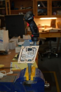
Here is what the completed assembly looks like, sans cover:

All that’s left is to fab the front cover for the NWS/AP lever and it’ll be totally complete.

Until next time, thanks for reading!