DIY Cockpit Project

Articles related to my DIY Cockpit project.

The past couple of weeks has brought some good progress to the simulator hardware.  It’s still not flyable yet, but it’s a lot closer than it was in December!

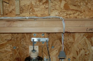
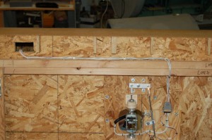
The main wiring harness for the pitch & roll axes gimbal and the stick wiring was installed:

I used cable clamps to attach the harness to the underside of the cockpit.  To separate the side from the center, you only need to unplug the harness from the gimbal assembly and remove one cable clamp.

It turned out nicely and while I should have combed out the wires (makes a better harness) it’s great for the prototype wiring.

Continue Reading

The goal was to be able to “fly” the 109F/X by the end of the year.  I didn’t make it unfortunately.  However, things are looking good for a 1st week of 2010!

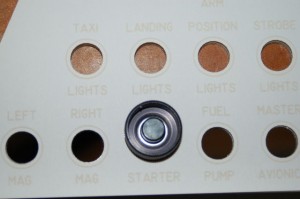
First up, here’s the completed edge-lit panel for the left sub-panel:
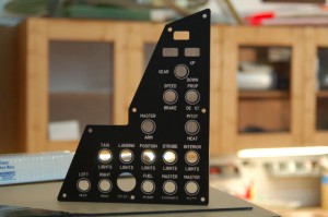
The only problem with the panel is due to a “mid-course” design change that I made.  Instead of making the edge-lit panel and metal back plate mounting separate, I decided to combine the two.  Since I had done all the panel lettering before I made this change, things on the bottom row kind of got a bit messed up.  It’s only really noticeable where the mounting screw passes through the STARTER legend.  If I was making this panel for someone else, I would remake it to correct the error.

The wiring on the pitch & roll axis gimbal is now completed.  Now that the flight grip has been wired up, it was time to finish out the wiring harness on the gimbal assembly:

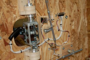
This adds the 16 wires that are needed by the flight grip and the nose wheel/AP disconnect lever.  Instead of using tie-wraps to create the new harness, I used waxed lacing cord and then used tie-wraps to attach the harness to nylon cable keeper blocks that have been attached to the gimbal base.  The last 6″ or so of the harness up to the DB25 connector is covered with a 1/2″ diameter black plastic split “loom” cover.  Makes it look nicer and prevents the wire from being abraded.

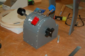
I had gotten the SFS box painted the previous evening and now it was time to mount the nose wheel steering/ap disconnect lever to the top of the box:
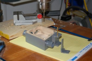
Instead of using a screw & bolt arrangement to hold the NWS/AP lever in, I decided to drill the hole in the side ears just a tiny bit under .125″ and use a brass pin to hold the lever in.  In order to properly set the pin, I turned my drill press into an impromptu arbor press by using a 3/32″ drill bit mounted backwards in the drill chuck.  I also gave the pin a slight bevel around the ends to make entering the mounting holes easier.  Here’s the result:
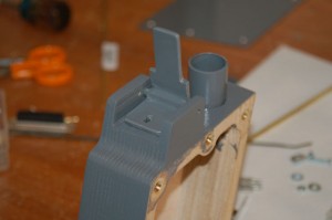
The pin pressed in just as I’d hoped and it won’t work itself out over time.  The good part about using the method I did is that the pin can be easily removed in the same manner it was installed if I need to replace or repair the lever in the future.

Now that the lever is in, it was time for the switch:
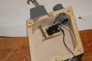
To actuate the micro-switch, I’m using a short length of #4-40 threaded rod as an actuator and a small spring to give it more “pull” than would be provided by the internal spring in the micro-switch.  I was able to thread the micro-switch actuating lever with a #4-40 tap.  There’s only enough metal for one thread or so, but it works really well!  I’m going to put a dab of Loc-Tite on it to help it out.

To retain the actuator rod, I used a brass acorn nut at the top:
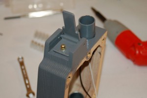
There is a small metal cover that still needs to be made that will cover the front portion of the NWS/AP lever.

The internal wiring of the box took some time to complete and there was not a whole lot of room in there:
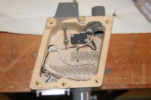
In order to make it more friendly to repair in the future, I decided to use terminal blocks to divide the SFS and grip wiring.  Using really small Euro style terminal strips allowed me to pull this off.    Even using the small terminal blocks it’s still VERY cramped in there!  Like all new wiring I’m doing, this is bound up using waxed lacing tape.  I cannot recommend this stuff enough!  Had I tried to use small wire-ties in here, it would have been a mess.  There just isn’t any room.
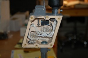
This is what the completed wiring layout looks like.  The grip wiring is a bit messier because I didn’t want to shorten any of the wires coming out of the rebuilt Suncom F-15 grip.

Here is what the completed assembly looks like, sans cover:
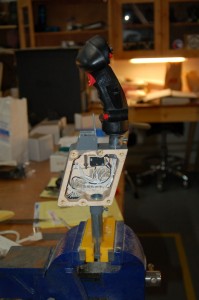
All that’s left is to fab the front cover for the NWS/AP lever and it’ll be totally complete.

Until next time, thanks for reading!
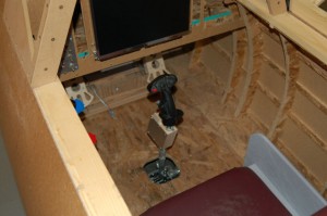
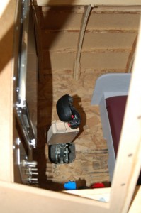
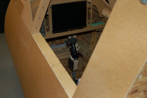
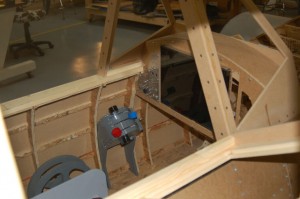
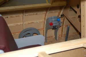
Here’s some pictures showing the test fitting of the new SFS box.

There are only two issues with this setup – the range of motion for the stick is far too great.  This can be cured with a little “motion restriction plate” which would be just a sheet of material with a square cut out of the center and placed at the stick base.  The second issue is that the springs in the gimbal are not strong enough to keep the stick centered.

The SFS box & grip really aren’t that heavy, but the account for a huge amount of force at the end of the stick gimbal mount.  Hopefully a new set of springs can cure this without too much bother.

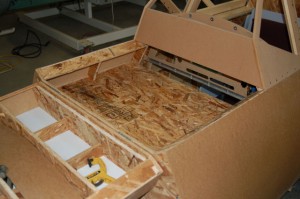
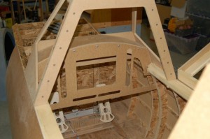
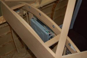
In order to have space for wiring and power supplies, I decided to add a forward deck to the cockpit ahead of the instrument panel:

There are two of these support assemblies.  Each one is made of two side ribs with “expanded” stringer notches, a single cross-piece and two doubler plates.  It’s assembled with six #10-24 screws on each side and the screws go into #10 T-nuts.  I’ll be making the drawings for these parts available to those that have purchased the project CD.

The deck itself is made of two pieces.  Each one is notched to accommodate the center rib as you can see in the photo.  The deck itself is just slightly higher than the instrument panel and a stiffening brace can be installed between the panel and the deck support if you feel the need.

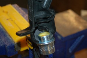
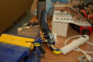
The grip I’m using for this cockpit is a rebuilt Suncom SFS F-15 Eagle grip.  In order to mount it to the 3/4″ EMT mounting post in the SFS box, I needed to attach a 3/4″ female EMT pipe fitting to the grip base.

I used a “steel epoxy” called JB Weld to ensure that the joint would be secure.  The fitting is mounted in the outside half of the grip.  By attaching it to half of the grip, I’ll be able to tear the grip down for maintenance if needed.

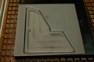
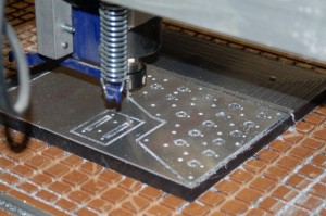
I was also able to get the edge-lit panel machined for the left sub-panel in the cockpit.  Here’s a picture of it right off the ‘bot:

The stock material is .25″ P95 translucent white acrylic.  I chose this because of it’s amazing light diffusing properties.  The pocket in the panel is .20″ deep, leaving me about .05″ of material left.

The next steps will involve creating an alignment jig for the laser and then the switch holes will be cut, the panel will be painted and then it will be lettered.

Finally, here’s a short video of the progress so far:

httpv://www.youtube.com/watch?v=-O3D-zryr8E

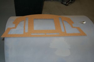
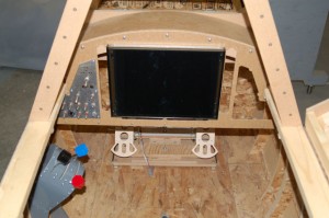
Today I was able to get the main instrument panel cut out.  It turned out really nice.

The whole point of the panel is to get it installed!
The panel has cutouts for a left & right sub-panel, a 15″ LCD PFD display, side bars for Garmin G1000 compatible controls and a button bar on the bottom.

The LCD has a smoked acrylic cover on it – the flash illuminates the LCD frame behind this cover.  You can’t see it under normal lighting conditions.

Here you can see a bit of how the custom LCD panel carrier is mounted into the instrument panel.  I’m really happy with how this turned out and with any luck I’ll be able to get the left sub-panel wired up and get its edge-lit panel created tomorrow.

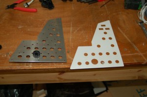
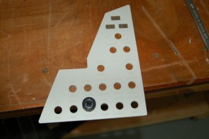
Yesterday I was able to get the metal parts for the left sub-panel cut out.

Because I only have one .125″ cutter left, I needed to go very slowly and take very small “bites” out of the material.  The panel is 6061-T6 aluminum, 0.062″ thick.  At the feed rate I used and taking .01″ per pass, it took four hours and forty-six minutes to cut.

Here’s the result of all that time:

I installed the “starter” push-button into the panel to see how it would fit with the test engraving of the light plate that I did.  The test light plate is made of card stock that I engraved on the Mini-24.  Below is a close up of the engraving.

It’s kind of hard to see in this picture, but the result is very nice.

The three rectangular cutouts at the top are for the landing gear indicators.

I decided when I finished my cockpit, I was going to call it an Me-109F/X.  This way I could get away with filling the panel with modern goodies.

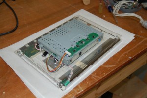
This includes a glass cockpit display.  In order to do this, I needed to rebuild an existing 15″ LCD panel so it would mount properly in the space I had available in the instrument panel.  Below is the result of that reconstruction

lcd_panel1

I move the panel components to a custom fabricated 1/8″ acrylic mounting bracket.

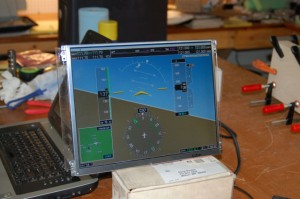
Here’s what it looks like showing a screen from a Garmin G1000 emulator that a friend of mine is working on:

lcd_panel2

I’m currently finalizing the layout of the instrument panel.  When it’s complete I’ll make sure to get pictures posted.

Most fighter aircraft don’t have seats that move fore & aft like a car seat does.  Instead, the seat is bolted in to place and the rudder pedal assembly is built to move in order to adjust for different sized pilots.

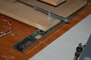
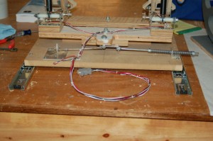
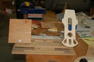
In order to do that in my cockpit, I mounted my rudder pedals on a pair of ball bearing drawer slides laid horizontally.

rudder_adjust1

The drawer slides are a little bit over 12″ long.

rudder_adjust2

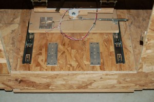
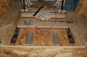
In order to “lock” the rudder pedals into place, I installed a pair of aluminum plates into the cockpit floor that are drilled to take 1/4″ locking “pins”.

rudder_adjust3

rudder_adjust4

It’s pretty simple, but it does get the job done!  At some point I’d like to be able to turn the two bolts I’m using as locking pins into actual pins that can be retracted from the cockpit itself, allowing adjustment without having to exit the cockpit and manipulate them from the front access hatch.

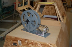
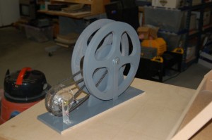
The other project that was finished is the trim & flap wheels:

wheels1

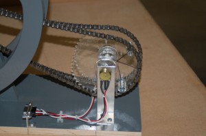
The wheels have a 12 tooth sprocket and they drive a 48 tooth sprocket that’s connected to a potentiometer.  This gives roughly four turns of the wheel to one turn of the pot.

wheels2

wheels3

I’m using #25 roller chain for this.  It’s similar to bicycle chain, but about half size.  The 48 tooth sprockets have travel restricting devices installed in order to prevent the high-torque output of the trim wheel from destroying the end stops in the potentiometers.

Here’s a pic of it installed in the prototype:

wheels4

It shouldn’t be too much longer before I actually get to flight test all this stuff. *laughs*

throttle_done1

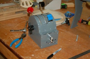
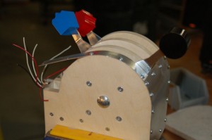
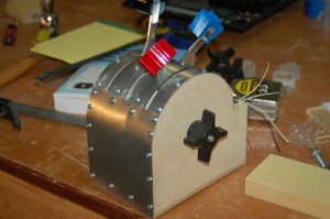
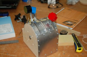
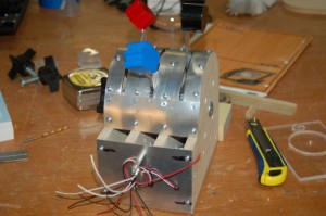
Well here’s the completed throttle quadrant.  I’m happy with how it turned out – which is surprisingly good considering how much I suck at metalworking. 🙂

throttle_done2

I’m using a standard DE9 connector for the three slide pots that are linked to each lever arm.

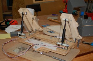
Right after I finished the throttle quadrant, I decided it was time to address the shortcomings in the rudder pedals that I built last summer.  I was very disappointed in both the toe brake mechanism as well as the size of the pedals.  I got lucky and found a pair of gas springs that had a 1-7/8″ stroke with a 40lb compression force.  They were surplus and ran me a whopping $1.99 each.

old_vs_new_pedal

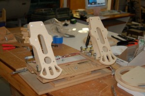
Here’s a comparison between the new pedal design and the old one.  The new pedal is on the right.

rudder_pedals1

The pedal design is based on a set of CAD drawings I found on the ‘net, drawn by a gent that goes by the nick Baloo.  The CAD drawings were entirely metric, which doesn’t do me much good here – I don’t dare mix measurement systems because I know for a fact it’ll come back and bite me in the ass some day.  I drew a new pedal design based on Baloo’s original drawing, but I increased the pedal length by about 1/2″.  They’re just about 12″ long now.  The pedals were cut from 1/2″ Baltic Birch, which is a 7+ layer high quality plywood.

rudder_pedals2

Here you can see the new gas spring setup.  The 40lb force required to actuate the gas spring gives a very realistic brake feel to the pedal.  I was very happy with the result.  I was also able to re-use the toe brake pots and actuator hardware without any changes.